Monday, February 22, 2010

Time Lapse Camera Controller

So, I finally made an Arduino project that does something other than measure the temperature...

As per usual, this project is an adaptation of the work of others - although mostly in concept for this project as I had to reverse engineer how to work my reed-relay and hook everything up.

This is a very simple setup, the camera does most of the work. I have a Canon Digital Rebel XT - it's a great camera, perfect for what I use it for. The camera has a 2.5mm stereo plug on the side that is intended for a remote shutter release (which of course Canon sells for 11 billion dollars). This project exploits that port by shorting the tip of the 2.5mm plug to the camera's internal ground, which in turn tells the camera to take a picture.

One major deviation in my implementation from the plans I had was that, as long as the camera is in autofocus mode, you only need to trip the tip. The barrel portion of the 2.5mm plug makes the camera focus (think about the two steps in depressing the shutter button) and the code I had as an example tripped this first, waited a second and then tripped the shutter. With the autofocus enabled it is not required to focus first, the camera seems to take care of that itself.

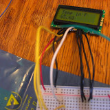
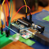
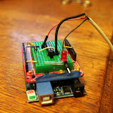
The whole system works by activating a reed-relay. With one pin of the relay connected to a digital pin on the arduino and the two pins that get connected by the reed-relay connected to the camera's ground and the tip of the 2.5mm plug... When the reed relay is activated by writing a "HIGH" level to the output pin the relay connects the shutter wire to the camera's ground and it takes a picture. By programming the arduino to activate the relay every X number of seconds, and leaving the camera on - it turns a regular digital camera into a time lapse camera. (All at a total cost of about 40 bucks, including the Arduino... Commercial things that do the same thing seem to cost about 200-300 bucks.)

Here's the first time-lapse I've made. I know it's boring. Deal with it.


Time Lapse Controller

Saturday, February 20, 2010

Arduino Project #2 - LCD Thermometer

I blew some cash on a pile of electronic components so I could do fun things with my Arduino. One of those was a small LCD display that I was eager to muck around with. I am thoroughly entertained by having an LCD because it makes the Arduino totally portable and capable of displaying information for me - rather than blinking and LED or changing its color to show changes in some variable.

So first I had to solder up the connections from the LCD board so I could connect them to the Arduino. This was no simple task for a rookie-solderer at a 1mm pitch... The only hookup wire I have is stranded and the pads had holes that were too small for the full size of the wire. So I had to cut out three of the strands from the wire and then put some heatshrink on the ends to make sure the little stubs didn't cause shorts across the pins. They aren't very pretty but I think for a prototyping board I did ok.

Displaying anything to and LCD requires six inputs/outputs, a +5 voltage supply, a variable voltage supply (for contrast control via a potentiometer), and of course a good ground connection. Once all the wires were soldered to the board I was stuck trying to figure out how to make the damn thing do something. I messed around with it for about two hours the first night before finally breaking down, dismantling the whole thing, posting my questions to the Arduino forum and going to bed.

This morning, there were some great replies that answered all my questions. My problem was two-fold. One, there are three control wires. One that tells the display you are about to write something, one that enables the writing, and one that tells the display controller if you are reading from it or writing to it. I wasn't sure what to do with the read/write pin so I had left in unconnected... My Arduino brethern gracefully informed that this pin needs to be grounded if it's not being used. So, I set up that connection, fired up the board - and still just a bunch of filled boxes - no text. So I started to play with the contrast and lo and behold I had the contrast so high that I couldn't see the text...

After playing with displaying a few messages I hooked up the thermistor from my last project and made the whole thing into an overly complicated thermometer. Really. Why am I so excited about a 50 dollar thermometer? Well, for one thing I built the damn thing myself which is pretty kickass. Another thing is it provides temp readouts in real-time to two (sometimes four - but I think that's a bug) decimal places... Also, did I mention that I built it?

Here are some photos:

Arduino Thermometer

One of these projects I'll get around to figuring out the blogger interface well enough to combine my pictures and text. But who am I kidding, no one reads this anyway...

Friday, February 12, 2010

First Arduino Project!

I bought an Arduino a while back and haven't really done anything with it until today...

From Arduino Mug Heater Temp Gauge


Frustrated with working on my thesis I decided to implement and idea I had about an arduino project. I have a mug-heater that sits on my desk to keep my coffee warm when I forget about (nothing is worse than grabbing for a shot of coffee and coming back with an icy-cold bleh).

Well, actually, I one of those candle-warmer things that you use to make candles smell nice without burning them that I use as a coffee-warmer because Bed-Bath and Beyond did not have any mug-warmers when I went looking for one and the clerk said that he thought a candle-warmer would be fine. Generally it is, except that it takes a long time to heat up and it gets a little too hot for my liking...

So I decided that I would use a 10k thermistor, a tri-color LED and my Arduino to make a gauge that would tell me how hot the warmer plate is. Naturally I could have just left the arduino plugged in with the serial monitor up and paid attention to it to find out the temps from the thermistor - but if I can't remember that I have coffee, what do you think the chances are that I will remember to check an extra window?

Since the Arduino is open source and the Arduino community consists of generally awesome people who know MUCH more about all of this than I do I was able to find a great function that converts the resistance values from the thermistor into Fahrenheit temperatures. (Really, it's amazing, no look-up table, very lightweight and effective.) I then run the temp value through an 'if' statement and determine which of the three leads on the LED to light up. Blue is for temperatures below 90; green is for temperatures between 90 and 110; and red is for temps above 110.

Here are some photos:

Arduino Mug Heater Temp Gauge

Here is the code for the whole project:
The 'Thermistor' function was taken from: http://www.arduino.cc/playground/ComponentLib/Thermistor2
The rest I wrote myself - my apologies for the lack of comments.
#include

int RED = 2;
int GREEN = 3;
int BLUE = 4;

int THERM = 1;

double Thermistor(int RawADC) {
double Temp;
Temp = log(((10240000/RawADC) - 10000));
Temp = 1 / (0.001129148 + (0.000234125 * Temp) + (0.0000000876741 * Temp * Temp * Temp));
Temp = Temp - 273.15; // Convert Kelvin to Celcius
Temp = (Temp * 9.0)/ 5.0 + 32.0; // Convert Celcius to Fahrenheit
return Temp;
}

void setup() {
Serial.begin(300);
pinMode(RED,OUTPUT);
pinMode(GREEN, OUTPUT);
pinMode(BLUE, OUTPUT);
}

void loop() {
Serial.println(Thermistor(analogRead(THERM))); // display Fahrenheit
delay(1000);
if (Thermistor(analogRead(THERM)) <>
digitalWrite(RED, LOW);
digitalWrite(GREEN, LOW);
digitalWrite(BLUE, LOW);
digitalWrite(BLUE, HIGH);
}
else if (Thermistor(analogRead(THERM)) > 90 && Thermistor(analogRead(THERM)) <>
digitalWrite(RED, LOW);
digitalWrite(GREEN, LOW);
digitalWrite(BLUE, LOW);
digitalWrite(GREEN, HIGH);
}
else {
digitalWrite(RED, LOW);
digitalWrite(GREEN, LOW);
digitalWrite(BLUE, LOW);
digitalWrite(RED, HIGH);
}
}