Tuesday, September 21, 2010

Mug Warmer Arduino Project

A few weeks ago I posted about building a mug heater that was controlled by an Arduino reading from some sensor values.  In this post I’m going to try and put together my notes and photos from the build project…

One of my first Arduino projects was to use a thermistor to sense the temperature of the warming plate and then change the color of an RGB LED accordingly.  The mug warmer project was certainly inspired in part by this initial testing – that and the fact that my coffee always gets too hot and I tend to leave the heater on when I leave the room (which I’m pretty sure is a fire hazard).

Here’s the Mug Heater in its current state, it’s fully operational and has been a nice addition to my desktop, I just haven’t had time to dress the wires properly and make it all look nice.

Mug Heater Project 2010-09-21 002

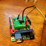
The project consists of four primary components.  The whole thing is controlled by an Arduino Pro (5V/16Mhz).  The power to the mug heater is controlled by another Sparkfun product that I really like – the Relay Control Board.  Here are two boards mounted in an enclosure I bought at the local Radio Shack when they went out of business:

Mug Heater Project 2010-09-16 003I had to grind out some rather annoying mounting posts that were in the bottom of the enclosure so I could glue in some standoffs that fit the boards. The one nice thing is that the enclosure has vertical slots on the sides to hold perf boards – because I quickly realized that I would need a custom one of those.

So I busted out my trusty Dremel tool and cut out a piece of perf board to fit across the enclosure.  I had to cut out for access to the control and power supply ports on the relay board as well as to get around the screws that hold it in.  I was trying to keep the board as large as possible since I wasn’t really sure how much room I was going to need.

Mug Heater Project 2010-09-16 001

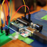
Two sensors, two LEDs, and the power switch are located inside the mug heater housing.  Each of these needed to be connected to one of the I/O pins on the Arduino.  All wired up the perf board looks something like this:

Mug Heater Project 2010-09-17 014

At this point in the project I hooked everything up and started testing the whole thing out…  Which led to this face:

Mug Heater Project 2010-09-17 006

Mug Heater Project 2010-09-16 008

There were several problems…  The most concerning was the weird power surge that kept causing my computer reset.  I had lots of problems with mounting LEDs and sensors.  (Bear in mind this is the first time I’ve ever built something that would be dedicated to one job and actually in an enclosure of some time so all of this was new…)  At this point I decided to take most everything I had done apart and start over.  I installed LED clips for the LEDs so they wouldn’t just be glued in place.  I soldered jumpers to the sensors and the LED pins so I could disconnect those wires more easily.  I also got the Dremel out again and cut out a large portion of the bottom and back of the mug-warmer enclosure in order to make the wire management bearable.  Some photos:

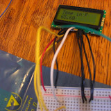
Jumpers attached to the photocell:


Mug Heater Project 2010-09-17 008

The cutout back so I can see what is going on and have room for all the wires:

Mug Heater Project 2010-09-18 004

I also re-glued the mounts for the Arduino and drilled a third hole in the enclosure so I could plug the FTDI in and upload new programs/get serial data on the computer with the board in the enclosure, this made my life much better!

Mug Heater Project 2010-09-17 013

In the above picture you can also see the nifty power connector I soldered on, because removable wires make me happy.

Mug Heater Project 2010-09-17 011

Here’s your reward for scrolling this far:

Also, the project code:

//Define LED Pin Numbers
int RED_LED = 3;
int GREEN_LED = 5;
int BLUE_LED = 6;
int BRIGHTNESS = 15;

// Define pin number that thermistor will be attached to
int TEMP_PIN = 2;

// Define pin number that the photoresistor will be attached to
int PHOTO_PIN = 0;

// Define pin number for relay trigger
int RELAY = 8;
boolean Relay_State = false;

// Temperature values for cutoffs
int HIGH_TEMP = 170;
int LOW_TEMP = 130;

// I copied this function from the Arduino tutorial on using a thermistor available at www.arduino.cc
// Whomever wrote it, it's fantastic and I thank you!
double Thermistor(int RawADC) {
  double Temp;
  Temp = log(((10240000/RawADC) - 10000));
  Temp = 1 / (0.001129148 + (0.000234125 * Temp) + (0.0000000876741 * Temp * Temp * Temp));
  Temp = Temp - 273.15;            // Convert Kelvin to Celcius
  Temp = (Temp * 9.0)/ 5.0 + 32.0; // Convert Celcius to Fahrenheit
  return Temp;
}

double getTemp() // I got sick of typing all this out every time I needed the temperature...
{
    return Thermistor(analogRead(TEMP_PIN));
}

boolean MugPresent() {  //Function returns a true value if the analogRead of the Photocell is less than 10, which based on my testing is a reasonable threshold...
  if (analogRead(PHOTO_PIN) > 10)
  { return false; }
  else
  { return true; }

}

void Debug()  // I hate typing things twice, this is convienient.
{
  Serial.println("DEBUG DATA");
  Serial.println(getTemp());
  Serial.println(analogRead(PHOTO_PIN));
  if (Relay_State == false)
    Serial.println("RELAY OFF");
  else
    Serial.println("RELAY ON");
}

void RelayControl() {
  if(getTemp() < LOW_TEMP && Relay_State == false)
  { digitalWrite(RELAY, HIGH); Relay_State = true; }
  else if(getTemp() > HIGH_TEMP && Relay_State == true)
  { digitalWrite(RELAY, LOW); Relay_State = false; }
}

void LEDColor() {
  if(getTemp() < LOW_TEMP)
  {
    analogWrite(RED_LED, 0);
    analogWrite(GREEN_LED, 0);
    analogWrite(BLUE_LED, BRIGHTNESS);
  }
  else if (getTemp() > LOW_TEMP && getTemp() < HIGH_TEMP)
  {
    analogWrite(RED_LED, 0);
    analogWrite(GREEN_LED, BRIGHTNESS);
    analogWrite(BLUE_LED, 0);  
  }
  else if (getTemp() > HIGH_TEMP)
  {
    analogWrite(RED_LED, BRIGHTNESS);
    analogWrite(GREEN_LED, 0);
    analogWrite(BLUE_LED, 0);
  }
}

void setup(void) {
  Serial.begin(9600);
  Serial.println("Serial Started");
  pinMode(PHOTO_PIN, INPUT);
  pinMode(TEMP_PIN, INPUT);
  pinMode(RED_LED, OUTPUT);
  pinMode(GREEN_LED, OUTPUT);
  pinMode(BLUE_LED, OUTPUT);
  pinMode(RELAY, OUTPUT);

  digitalWrite(RED_LED, LOW);
  digitalWrite(GREEN_LED, LOW);
  digitalWrite(BLUE_LED, LOW);
  digitalWrite(RELAY,LOW);
  //9-22-2010 I added this function to make the warming plate warm up once before switching on and off, that way I can turn it on, go get my coffee and come back with a warm plate to set it on.
  while(getTemp() < HIGH_TEMP)
  {
     if (!Relay_State)
     {
       digitalWrite(RELAY,HIGH); Relay_State = true;
       Debug();
     }
  }
}

void loop() {
  LEDColor();
  while (MugPresent())
  {
     RelayControl();
     Debug();
     LEDColor();
     delay(1600);
  }
  Debug();
  digitalWrite(RELAY, LOW); Relay_State = false;
  delay(1600);
}

Thursday, September 2, 2010

Sensor Enabled Mug Heater – The Beginning!

I have a dream.  A dream that one day, I will have a mug heater that will not only keep my coffee toasty but regulate its temperature.  I have a dream that there will also be a sensor that will turn the heating element off when there is no mug to be heated.  I have a dream, I am a geek – that dream is about to come true.

Hey, if Glen Beck can steal words from greater men than himself, so can I…

Here’s a quick video about my newest Arduino project – the Sensor Enabled Mug Heater:

Monday, May 17, 2010

95 Percent Confidence Interval for Proportions in Excel

I worked  this out a while ago because I needed to do these for graphs in my masters thesis.  If anyone can use them go for it, although I would appreciate being credited somehow if you use them in a publication of any sort.
Bear in mind I am an archaeologist by trade and make no claim to these being absolutely correct.  If anyone notices a problem with them please let me know!  They seem to work pretty well.
95 Percent Confidence Interval for Proportions Formula for Excel

=((SQRT(((1-(U3/$U$7))*(1-(1-(U3/$U$7)))/U3))*1.96)*100)

This works where the cell defined as U3 = n (# of Xs in a Sample) and $U$7 = N (Total sample size).  The static reference allows the formula to be copied down a column and keep the total sample size fixed in all calculations.  The non-static (U3) reference will update (in excel) down the column to use the value from the appropriate (row-adjacent) n value.

The formula is derived as follows: (Formula values taken from spreadsheets that PTM built, I just spread them out and made them excel friendly.

1-p = 1-(n/N)
q = 1-p = 1-(1-(n/N)
p*q = (1-(n/N)) * (1-(1-(n/N))
(p*q)/n = ((1-(n/N)) * (1-(1-(n/N)))/n
sqrt((p*q)/n) = sqrt(((1-(n/N)) * (1-(1-(n/N)))/n)
Z(sqrt((p*q)/n)) = (sqrt(((1-(n/N)) * (1-(1-(n/N)))/n))*1.96
95% CI = Z(sqrt((p*q)/n))*100 = ((sqrt(((1-(n/N)) * (1-(1-(n/N)))/n))*1.96)*100

This final formula was copied and pasted into an excel cell, and made into a formula by pre-pending an equals sign to the front, yielding:

=((SQRT(((1-(n/N))*(1-(1-(n/N)))/n))*1.96)*100)

The n and N values were then replaced with the appropriate cell references, yielding:

=((SQRT(((1-(U3/$U$7))*(1-(1-(U3/$U$7)))/U3))*1.96)*100)

The final formula.

The values calculated by the final formula were cross checked against the values my thesis advisor derived by calculating the value across several columns and they match up perfectly.  I suggest that the calculated CI values be rounded to the nearest whole integer because it makes them easier to see.

Friday, April 30, 2010

So they’re somewhere that I can find them:

The world in which you were born is just one model of reality.  Other cultures are not failed attempts at being you; they are unique manifestations of the human spirit.
-Wade Davis

"It appears to me (whether rightly or wrongly) that direct arguments against christianity and theism produce hardly any effect on the public; and freedom of thought is best promoted by the gradual illumination of men's minds which follows from the advance of science."
-Darwin

"Out of clutter, find simplicity. Out of discord, find harmony. In the middle of difficulty lies opprotunity"
-Einstein

"Objectivity cannot be equated with mental blankness; rather, objectivity resides in recognizing your preferences and then subjecting them to especially harsh scrutiny — and also in a willingness to revise or abandon your theories when the tests fail (as they usually do)."  — Stephen Jay Gould

The most important scientific revolutions all include, as their only common feature, the dethronement of human arrogance from one pedestal after another of previous convictions about our centrality in the cosmos.
Steven Jay Gould

Your duty is to be; and not be this or that.
Ramana Maharshi

Everything exists. Nothing has value.
E.M. Forster

I never saw a wild thing sorry for itself.
A small bird will drop frozen dead from a bough
Without ever having felt sorry for itself.
D.H. Lawrence

Monday, February 22, 2010

Time Lapse Camera Controller

So, I finally made an Arduino project that does something other than measure the temperature...

As per usual, this project is an adaptation of the work of others - although mostly in concept for this project as I had to reverse engineer how to work my reed-relay and hook everything up.

This is a very simple setup, the camera does most of the work. I have a Canon Digital Rebel XT - it's a great camera, perfect for what I use it for. The camera has a 2.5mm stereo plug on the side that is intended for a remote shutter release (which of course Canon sells for 11 billion dollars). This project exploits that port by shorting the tip of the 2.5mm plug to the camera's internal ground, which in turn tells the camera to take a picture.

One major deviation in my implementation from the plans I had was that, as long as the camera is in autofocus mode, you only need to trip the tip. The barrel portion of the 2.5mm plug makes the camera focus (think about the two steps in depressing the shutter button) and the code I had as an example tripped this first, waited a second and then tripped the shutter. With the autofocus enabled it is not required to focus first, the camera seems to take care of that itself.

The whole system works by activating a reed-relay. With one pin of the relay connected to a digital pin on the arduino and the two pins that get connected by the reed-relay connected to the camera's ground and the tip of the 2.5mm plug... When the reed relay is activated by writing a "HIGH" level to the output pin the relay connects the shutter wire to the camera's ground and it takes a picture. By programming the arduino to activate the relay every X number of seconds, and leaving the camera on - it turns a regular digital camera into a time lapse camera. (All at a total cost of about 40 bucks, including the Arduino... Commercial things that do the same thing seem to cost about 200-300 bucks.)

Here's the first time-lapse I've made. I know it's boring. Deal with it.


Time Lapse Controller

Saturday, February 20, 2010

Arduino Project #2 - LCD Thermometer

I blew some cash on a pile of electronic components so I could do fun things with my Arduino. One of those was a small LCD display that I was eager to muck around with. I am thoroughly entertained by having an LCD because it makes the Arduino totally portable and capable of displaying information for me - rather than blinking and LED or changing its color to show changes in some variable.

So first I had to solder up the connections from the LCD board so I could connect them to the Arduino. This was no simple task for a rookie-solderer at a 1mm pitch... The only hookup wire I have is stranded and the pads had holes that were too small for the full size of the wire. So I had to cut out three of the strands from the wire and then put some heatshrink on the ends to make sure the little stubs didn't cause shorts across the pins. They aren't very pretty but I think for a prototyping board I did ok.

Displaying anything to and LCD requires six inputs/outputs, a +5 voltage supply, a variable voltage supply (for contrast control via a potentiometer), and of course a good ground connection. Once all the wires were soldered to the board I was stuck trying to figure out how to make the damn thing do something. I messed around with it for about two hours the first night before finally breaking down, dismantling the whole thing, posting my questions to the Arduino forum and going to bed.

This morning, there were some great replies that answered all my questions. My problem was two-fold. One, there are three control wires. One that tells the display you are about to write something, one that enables the writing, and one that tells the display controller if you are reading from it or writing to it. I wasn't sure what to do with the read/write pin so I had left in unconnected... My Arduino brethern gracefully informed that this pin needs to be grounded if it's not being used. So, I set up that connection, fired up the board - and still just a bunch of filled boxes - no text. So I started to play with the contrast and lo and behold I had the contrast so high that I couldn't see the text...

After playing with displaying a few messages I hooked up the thermistor from my last project and made the whole thing into an overly complicated thermometer. Really. Why am I so excited about a 50 dollar thermometer? Well, for one thing I built the damn thing myself which is pretty kickass. Another thing is it provides temp readouts in real-time to two (sometimes four - but I think that's a bug) decimal places... Also, did I mention that I built it?

Here are some photos:

Arduino Thermometer

One of these projects I'll get around to figuring out the blogger interface well enough to combine my pictures and text. But who am I kidding, no one reads this anyway...

Friday, February 12, 2010

First Arduino Project!

I bought an Arduino a while back and haven't really done anything with it until today...

From Arduino Mug Heater Temp Gauge


Frustrated with working on my thesis I decided to implement and idea I had about an arduino project. I have a mug-heater that sits on my desk to keep my coffee warm when I forget about (nothing is worse than grabbing for a shot of coffee and coming back with an icy-cold bleh).

Well, actually, I one of those candle-warmer things that you use to make candles smell nice without burning them that I use as a coffee-warmer because Bed-Bath and Beyond did not have any mug-warmers when I went looking for one and the clerk said that he thought a candle-warmer would be fine. Generally it is, except that it takes a long time to heat up and it gets a little too hot for my liking...

So I decided that I would use a 10k thermistor, a tri-color LED and my Arduino to make a gauge that would tell me how hot the warmer plate is. Naturally I could have just left the arduino plugged in with the serial monitor up and paid attention to it to find out the temps from the thermistor - but if I can't remember that I have coffee, what do you think the chances are that I will remember to check an extra window?

Since the Arduino is open source and the Arduino community consists of generally awesome people who know MUCH more about all of this than I do I was able to find a great function that converts the resistance values from the thermistor into Fahrenheit temperatures. (Really, it's amazing, no look-up table, very lightweight and effective.) I then run the temp value through an 'if' statement and determine which of the three leads on the LED to light up. Blue is for temperatures below 90; green is for temperatures between 90 and 110; and red is for temps above 110.

Here are some photos:

Arduino Mug Heater Temp Gauge

Here is the code for the whole project:
The 'Thermistor' function was taken from: http://www.arduino.cc/playground/ComponentLib/Thermistor2
The rest I wrote myself - my apologies for the lack of comments.
#include

int RED = 2;
int GREEN = 3;
int BLUE = 4;

int THERM = 1;

double Thermistor(int RawADC) {
double Temp;
Temp = log(((10240000/RawADC) - 10000));
Temp = 1 / (0.001129148 + (0.000234125 * Temp) + (0.0000000876741 * Temp * Temp * Temp));
Temp = Temp - 273.15; // Convert Kelvin to Celcius
Temp = (Temp * 9.0)/ 5.0 + 32.0; // Convert Celcius to Fahrenheit
return Temp;
}

void setup() {
Serial.begin(300);
pinMode(RED,OUTPUT);
pinMode(GREEN, OUTPUT);
pinMode(BLUE, OUTPUT);
}

void loop() {
Serial.println(Thermistor(analogRead(THERM))); // display Fahrenheit
delay(1000);
if (Thermistor(analogRead(THERM)) <>
digitalWrite(RED, LOW);
digitalWrite(GREEN, LOW);
digitalWrite(BLUE, LOW);
digitalWrite(BLUE, HIGH);
}
else if (Thermistor(analogRead(THERM)) > 90 && Thermistor(analogRead(THERM)) <>
digitalWrite(RED, LOW);
digitalWrite(GREEN, LOW);
digitalWrite(BLUE, LOW);
digitalWrite(GREEN, HIGH);
}
else {
digitalWrite(RED, LOW);
digitalWrite(GREEN, LOW);
digitalWrite(BLUE, LOW);
digitalWrite(RED, HIGH);
}
}